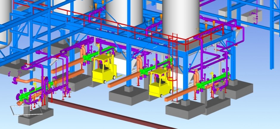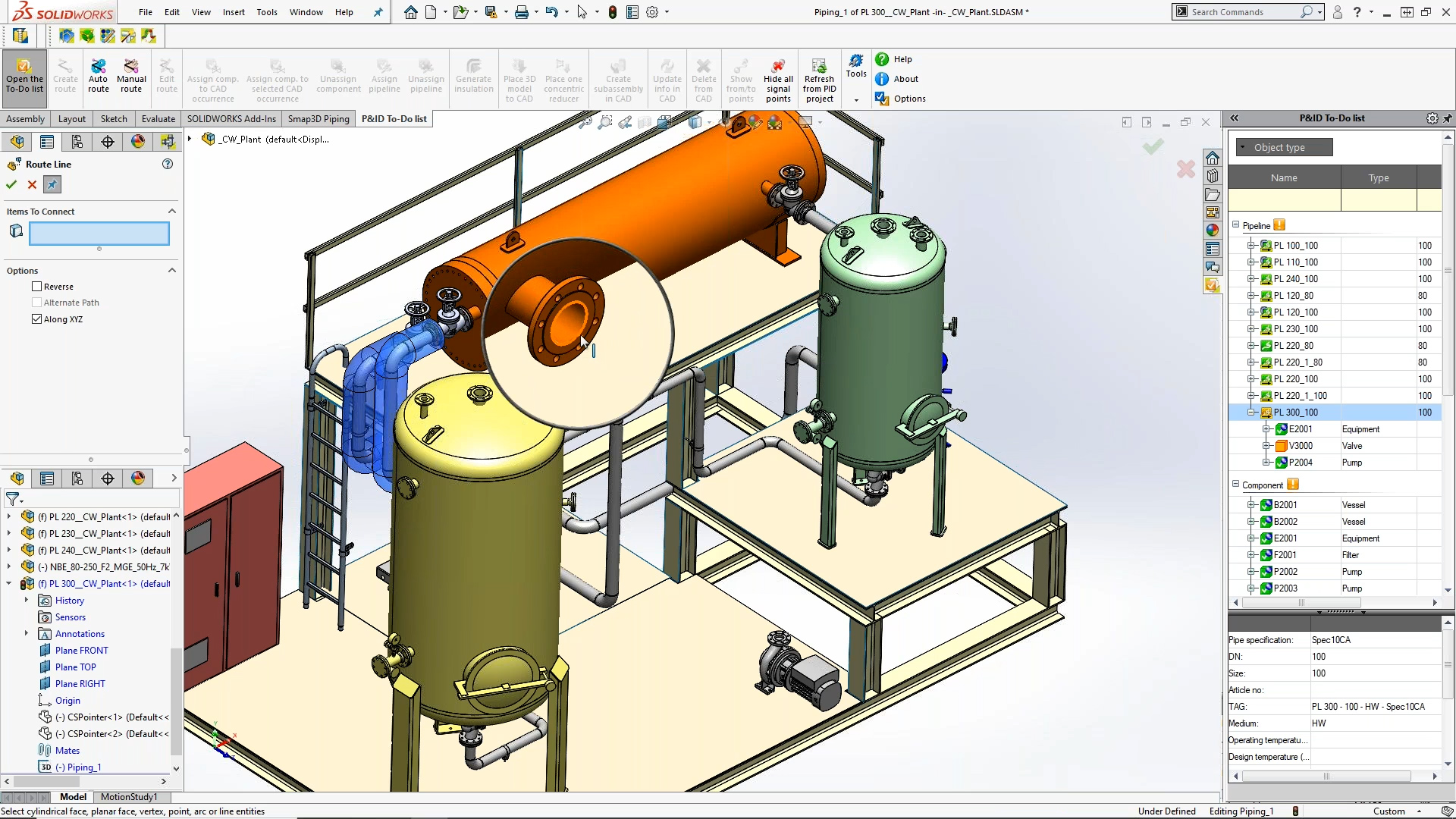

Piping Layout Software Software For Plant
The experienced piping designer, with the knowledge and capability of3D software for plant design across all disciplines. In the past, a computer stress analysis, including the development of input data and the interpretation of the output, could be expensive and time-consuming if numerous iterations of computer runs were needed to arrive at an acceptable system design. However, it is the piping designer’s responsibility to ensure that the final stress analysis results are incorporated into the final pipe support and pipe routing design. The piping stress analyst translates and enters the piping design data into the computer, reviews the output data, and if the system is too rigid, may suggest appropriate corrective redesigns.
Importing and using our PVC Components is easy and hassle-free. You can use SketchUp to construct your PVC project, use it to view some of our freely available PVC plans, or just play around. Vents, drains and utility connections shall be arranged to prevent unintentional or undetected leakage.SketchUp is a free, easy to use, 3-Dimensional sketching program provided by Trimble. Valves and flanges shall not be located inside vessel skirts. Piping at columns shall be located, where possible, radially about the column on the pipeway side. For this reason, the piping designer should be familiar with the commercially availablePiping Layout.
STRUCTURAL DESIGN OF ONSHORE PROJECTS USING STAADPRO SOFTWARE.Operability, from the standpoint of operating personnel, means being able to perform daily functions in an efficient manner. The piping designer should work closely with the structural engineer in the spacing of the pipe rack supports and the method of intermediate support to prevent pipe sagging.Multitex Pipeline and Process Piping best engineers and consultants consult work to. Piping on pipe racks should be routed using bottom-of-pipe (BOP) elevations. Banks of parallel pipelines at different elevations should be staggered horizontally and spaced sufficiently apart to permit independent pipe supports for each line. Piping should be routed such that the support designer can make use of the surrounding structure to provide logical points of support, anchors, guides, or restraints, with ample space for the appropriate hardware.
Today the trend is toward virtual reality. Formerly in difficult cases, models or even full-size mock-ups have been used as design aids. Sometimes input from construction, start-up, and vendor personnel is needed. To ensure success, the designer, system engineer, and operating personnel work out the final arrangement. Safety-related equipment and valves that are required to be operated during an emergency or to perform critical system functions must be accessible without exception. The designer cannot make every valve and instrument ideally accessible, butWill concentrate on those requiring the most frequent operation.
These hazards could include any piping components that presented themselves as ‘‘head knockers,’’ ‘‘knee knockers,’’ or trippers. It is the responsibility of the piping designer to place equipment, valves, and other piping components in such positions that they do not create hazards. It is recognized that plant operating personnel will occasionally have to reach for a drain from a kneeling position or a vent valve from a ladder, but these are infrequent operations and as such can be tolerated.Stairs, platforms, ladders, aisles, means-of-egress aisleways, and minimum headroom allowances designed in accordance with OSHA will provide a safe place to work. The position of the valve handwheel should be such that the force necessary to operate it can be applied without strain or undue contortions or interference from valves, lines, or other equipment. In general, an operable valve or instrument is one that can be readily reached when standing at grade or on an elevated floor or platform provided for that purpose. Additional considerations are discussed in other sections of this chapter.
Therefore, the CAD system must support this type of activity. However, this may be too restrictive, and it is not meant to rule out any perfectly safe arrangement of valves at face level ifPiping layout is not done in isolation and must interface design information and drawings from other piping designers as well as other disciplines. This same principle applies to hazardous and toxic fluids. Steam system valves must not be placed at face level in the horizontal position since a packing gland leak may blow steam into the face of an operator if this were a superheated steam leak, the vapor would not be visible. The designer should make every effort to keep such projections out of heights of 4¹⁄₂ to 6 ft (1.5 to 2 m), or specifically at face level. When this cannot be done, the designer should ascertain that the stem does not project into an access area and become a hazard.
In addition, it also greatly increases the storage requirements since many drawings are duplicated, perhaps numerous times. This does not allow the designer to see the active data of other designers. Without this capability in the CAD software or for personal computers which are not in a network, the data from other designers must be copied and incorporated into the designer’s file. For personal-computer-based CAD systems, this requires that they be part of some type of local or wide-area network. This allows one designer to see the file of another designer, as if it were part of his or her file however, the data cannot be changed. Systems which have this capability often refer to it as a reference file capability.
This is the role of applications software developed specifically for piping which automatically generates and manages this information during the creation of the drawing. However, note that merely having a basic database capability does not mean that it can be effectively used for extracting data from piping drawings. It is even possible to generate the input to the piping stress analysis program from a piping isometric. With this type of capability, bills of material can be generated automatically from the piping drawings.
Now, however, as the cost continues to decrease and the piping design industry in general increases its sophistication in the use of CAD, more effective uses of CAD are being made by placing the workstations right in the piping design groups. Centralized CAD groups working multiple shifts were often the norm with the installation of the large turnkey systems. This not only dramatically decreases the productivity of the drawing production process, but also greatly increases the possibility of errors.The precise method of implementing a CAD system is dependent on the company’s current organization and method of executing work.
Many CAD systems provide interactive 3D modeling capabilities, but these are not usually sufficient for 3D piping design. This approach can greatly increase the productivity of the whole design and drafting cycle.In fact, without interactive design capabilities, another step is added to the process for entering the data into the 3D model from the 2D design drawings. Instead of creating sketches which are then passed on to a drafter, the designer, using the CAD system and piping layout applications software, can create an electronic sketch which is very nearly a finished drawing, leaving very little to do in the way of drafting. But again, experience has shown that even more effective use can be made of the CAD system by training senior-level piping designers.


 0 kommentar(er)
